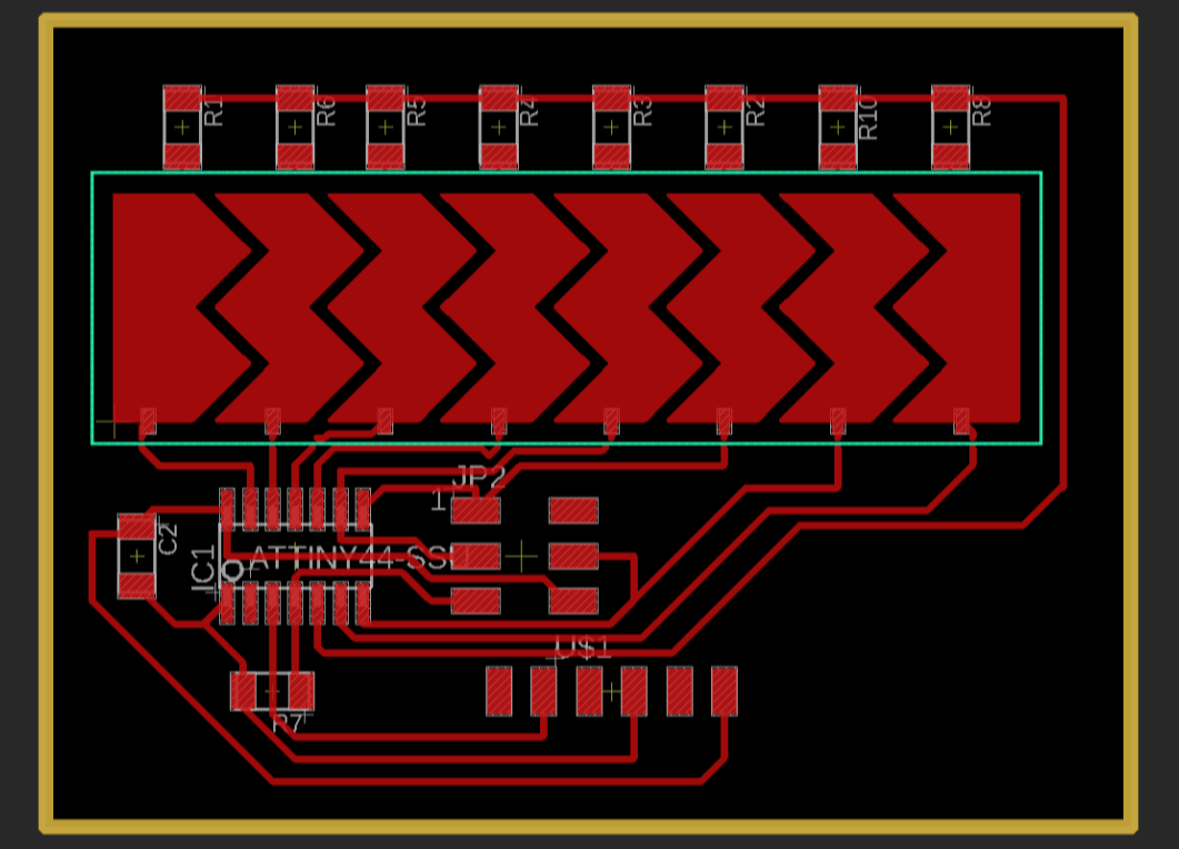
I routed it manually to get more ascetics.
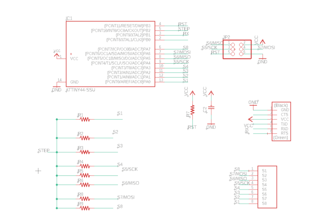
Eagle schematic.
Objectives
Individual Assignment
1)Measure something: add a sensor to a micro-controller board
that you have designed and read it.
Group Assignment
1)Probe an input device's analog levels and digital signals.
1.Flexible LED Matrix Ring by Honghao Deng.
2.Flapping Origami crane using shape memory Alloy.
3.Matt Keeter- Capacitive Multi-touch.
4.Color sensor based on RGB LED and photo transistor.
5.Touchpad by Matt Blackshaw.
6.ShArc: A Geometric Technique for Multi-Bend/Shape Sensing
7.Venous Materials: Towards Interactive Fluidic Mechanisms
8.Fabriccio: Touchless Gestural Input on Interactive Fabrics
Step Response Sensor,How it works?
A Step Response sensor, are input devices that act as a Heavyside Step Function; meaning, a change that goes from 0 to one in a very short period of time.
Capacitive Sensor:
The capacitance of a device is the ratio of the change in an electric charge in a system to the corresponding change in its electric potential 1.
Sometimes you put a dialectric material between the two plates of your capacitor . The capacitance of the system will vary in function of the conductivity of the material.
More details on this can be found in the following link.
After testing the concept with Neils board, and being able to see that the sensor responds to the variation of the material that was set between the two cooper plates.So I started of using Eagle to create the Slider and the circuit layout and milled it.
I routed it manually to get more ascetics.
Eagle schematic.

Stuffed the Micro controller(AtTiny84) and other Components.
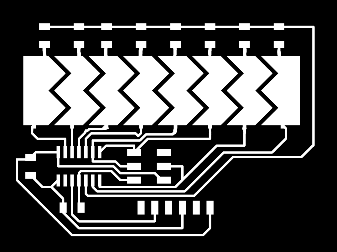
Generated the Monochrome Trace And Milled.
Programming The Board.
With Help of Referring one of our instructors code(link.) and help from Jojin and Saheen I updated the Neil's code.
// Lots of learning.
//Updated Neil"s Code
// 9600 baud FTDI interface
//
#include <SoftwareSerial.h>
SoftwareSerial mySerial(10, 9); // RX, TX
#include <avr/io.h
#include <util/delay.h>
#define output(directions,pin) (directions |= pin) // set port direction for output
#define set(port,pin) (port |= pin) // set port pin
#define clear(port,pin) (port &= (~pin)) // clear port pin
#define pin_test(pins,pin) (pins & pin) // test for port pin
#define bit_test(byte,bit) (byte & (1 << bit)) // test for bit set
#define charge_delay_1() _delay_us(1) // charge delay 1
#define settle_delay() _delay_us(100) // settle delay
#define char_delay() _delay_ms(10) // char delay
#define charge_port PORTB
#define charge_direction DDRB
#define charge_pin (1 << PB2)
#define ref (0 << REFS1) | (0 << REFS0) // reference voltage
#define sense7 (0 << MUX2) | (0 << MUX1) | (0 << MUX0) // PA0
#define sense6 (0 << MUX2) | (0 << MUX1) | (1 << MUX0) // PA1
#define sense5 (0 << MUX2) | (1 << MUX1) | (0 << MUX0) // PA2
#define sense4 (0 << MUX2) | (1 << MUX1) | (1 << MUX0) // PA3
#define sense3 (1 << MUX2) | (0 << MUX1) | (0 << MUX0) // PA4
#define sense2 (1 << MUX2) | (0 << MUX1) | (1 << MUX0) // PA5
#define sense1 (1 << MUX2) | (1 << MUX1) | (0 << MUX0) // PA6
#define sense0 (1 << MUX2) | (1 << MUX1) | (1 << MUX0) // PA7
#define down_threshold 700
#define up_threshold 750
int check_pin(unsigned char pin) {
unsigned char up_lo,up_hi,down_lo,down_hi;
int up_value, down_value, value;
//
// set the A/D pin
//
ADMUX = ref | pin;
//
// settle, charge, and wait 1
//
settle_delay();
set(charge_port, charge_pin);
charge_delay_1();
//
// initiate conversion
//
ADCSRA |= (1 << ADSC);
//
// wait for completion
//
while (ADCSRA & (1 << ADSC))
;
//
// save result
//
up_lo = ADCL;
up_hi = ADCH;
//
// settle, discharge, and wait 1
//
settle_delay();
clear(charge_port, charge_pin);
charge_delay_1();
//
// initiate conversion
//
ADCSRA |= (1 << ADSC);
//
// wait for completion
//
while (ADCSRA & (1 << ADSC))
;
//
// save result
//
down_lo = ADCL;
down_hi = ADCH;
//
// process result
//
up_value = 256 * up_hi + up_lo;
down_value = 256 * down_hi + down_lo;
value = (up_value + (1023 - down_value)) / 2;
return value;
}
void sense_pin(unsigned char pin, int *oldValue, char labelChar) {
int value = check_pin(pin);
if ((*oldValue == 1 && value > up_threshold) || (*oldValue == 0 && value < down_threshold)) {
mySerial.print(labelChar);
char_delay();
if (*oldValue) {
*oldValue = 0;
mySerial.print('0');
}
else {
*oldValue = 1;
mySerial.print('1');
}
char_delay();
mySerial.print('\n');
char_delay();
}
}
int main(void) {
mySerial.begin(9600);
//
// main
//
static int touch1, touch2, touch3, touch4, touch5, touch6, touch7, touch8;
touch1 = touch2 = touch3 = touch4 = touch5 = touch6 = touch7 = touch8 = 0;
//
// set clock divider to /1
//
CLKPR = (1 << CLKPCE);
CLKPR = (0 << CLKPS3) | (0 << CLKPS2) | (0 << CLKPS1) | (0 << CLKPS0);
//
// initialize output pins
clear(charge_port, charge_pin);
output(charge_direction, charge_pin);
//
// init A/D
//
ADMUX = ref; // Vcc ref
ADCSRA = (1 << ADEN) // enable
| (1 << ADPS2) | (1 << ADPS1) | (1 << ADPS0); // prescaler /128
ADCSRB = (0 << ADLAR); // right adjust
//
// main loop
//
while (1) {
//
// sense pins
//
sense_pin(sense0, &touch1, '0');
sense_pin(sense1, &touch2, '1');
sense_pin(sense2, &touch3, '2');
sense_pin(sense3, &touch4, '3');
sense_pin(sense4, &touch5, '4');
sense_pin(sense5, &touch6, '5');
sense_pin(sense6, &touch7, '6');
sense_pin(sense7, &touch8, '7');
}
}
Test 101. Yesss its returning +1 with pre-defined value to a pad And I need to work out the program to calibrate.
The RC522 RFID Reader module is designed to create a 13.56MHz electromagnetic field that it uses to communicate with the RFID tags (ISO 14443A standard tags). The reader can communicate with a microcontroller over a 4-pin Serial Peripheral Interface (SPI) with a maximum data rate of 10Mbps. It also supports communication over I2C and UART protocols.
The module comes with an interrupt pin. It is handy because instead of constantly asking the RFID module “is there a card in view yet? “, the module will alert us when a tag comes into its vicinity.
The operating voltage of the module is from 2.5 to 3.3V
Frequency Range 13.56 MHz ISM Band
Host Interface SPI / I2C / UART
Operating Supply Voltage 2.5 V to 3.3 V
Max. Operating Current 13-26mA
Min. Current(Power down) 10µA
Logic Inputs 5V Tolerant
Read Range 5 cm
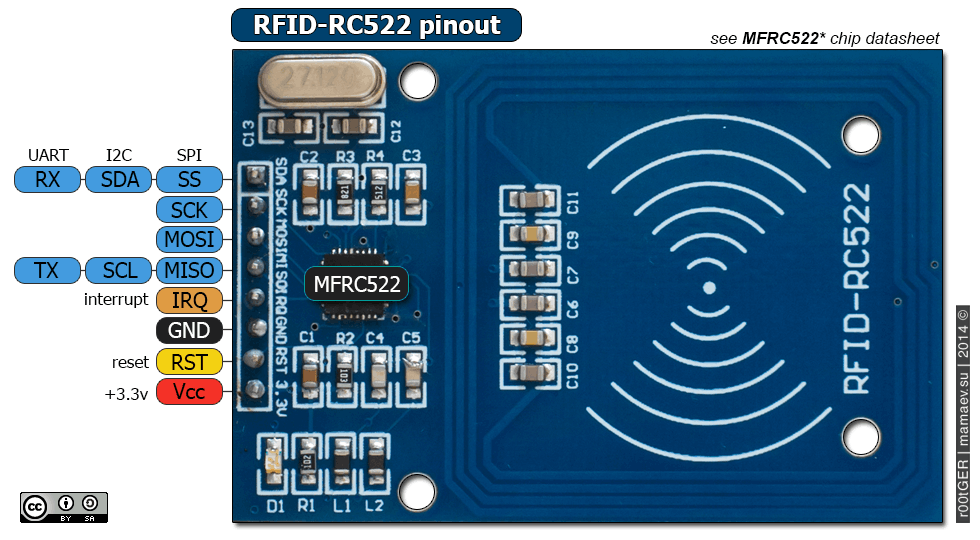
RFID PIN out.
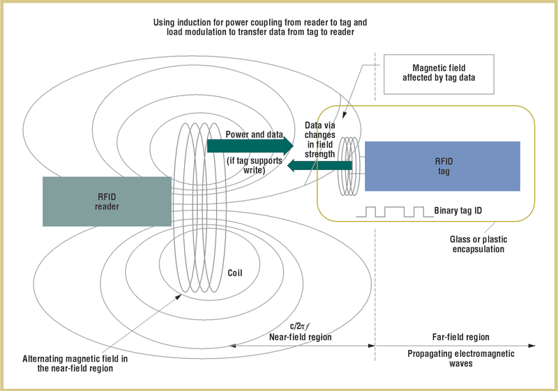
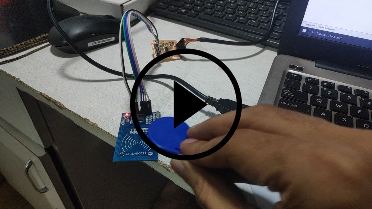
How RFID Works?
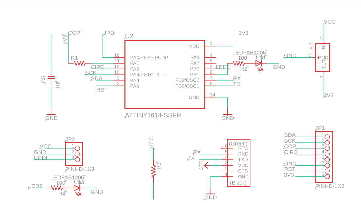
Schematic
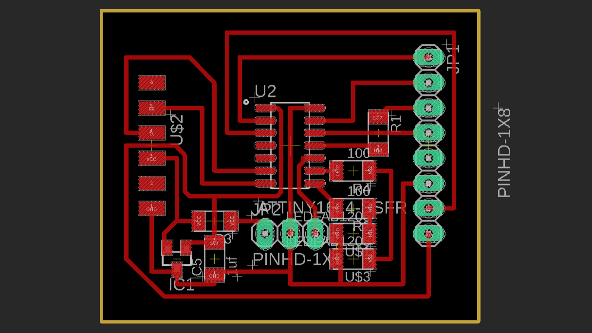
Board Routed.
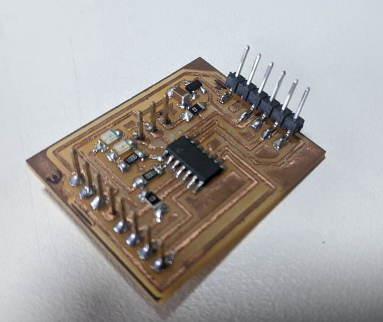
Stuffed Board
MFRC522 library which simplifies reading from and writing to RFID tags
https://github.com/miguelbalboa/rfid
#include <SPI.h
#include <MFRC522.h>
#define SS_PIN 0
#define RST_PIN 1
#define KEY_RETURN 0xB0 //The hex value for the return key is 0xB0.
MFRC522 mfrc522 ( SS_PIN, RST_PIN ) ;
char Enter = KEY_RETURN; //Return key is declared as Enter.
String readid;
String card1 = "a6c15673"; //Change this value to the UID of your card.
void setup( )
{
Serial.begin(115200);
SPI.begin();
mfrc522.PCD_Init();
pinMode(7, OUTPUT);
pinMode(6, OUTPUT);
}
void temp(byte *buffer, byte bufferSize)//function to store card uid as a string datatype.
{
readid = "";
for (byte i = 0; i < bufferSize; i++)
{
readid = readid + String(buffer[i], HEX);
}
}
void loop( )
{
if (!mfrc522.PICC_IsNewCardPresent())
{
return;
}
if (!mfrc522.PICC_ReadCardSerial())
{
return;
}
// mfrc522.PICC_DumpToSerial(&(mfrc522.uid)); // Display card details in serial Monitor.
temp(mfrc522.uid.uidByte, mfrc522.uid.size);
if (readid == card1)
{
Serial.println("haii abel");
digitalWrite(6, HIGH); // turn the LED on (HIGH is the voltage level)
delay(2000); // wait for a second
digitalWrite(6, LOW); // turn the LED off by making the voltage LOW
delay(2000); // wait for a
}
else
{ Serial.println("who the f*ck are you");
digitalWrite(7, HIGH); // turn the LED on (HIGH is the voltage level)
delay(2000); // wait for a second
digitalWrite(7, LOW); // turn the LED off by making the voltage LOW
delay(2000);
}
}
Person Identified. ;)
Created with Mobirise - Check it